> […] Continuing this trend, rounding as needed, and we end up with the series 10, 15, 22, 33, 47, and 68. Components built to the E6 standard have a 20% relative error tolerance, and if we look at the values again we’ll see a trend. Starting with 10 again and adding 20% error we end up with 12. Moving to 15 and subtracting 20% we get… wait for it… 12. Moving up from 15 we get 15 + 20% = 18 and 22 – 20% = 17.6. This trend repeats no matter what range of powers of 10 you use, as long as they are consecutive. So 47kΩ + 20% = 56400, while 68kΩ – 20% = 54400.
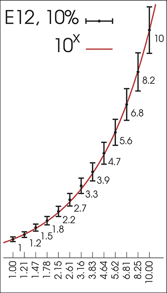
> Look again at the values 47 and 68. The max/min values overlap right about 56, don’t they? That sounds familiar. The E12 standard uses all of the same values as E6, but with 6 more values mixed in. These 6 additional values are roughly where the E6 values overlap, and now in order to cover the entire range our %-error is reduced to 10%. Starting again at 10, we have 10, 12, 15, 18, 22, 27, 33, 39, 47, 56, 68, and 82. The math holds true here as well, with the error values just slightly overlapping.
It's the 'tolerance overlap' concept that makes the numbers work, but I don't think I've ever seen it explained so clearly before.
This only works with perfect resistors, though. If your actual resistors have a fabrication tolerance, you might be more off. For example, if you need a 41 Ohm resistor, you can use a perfect 47 Ohm resistor from the E6-series, and you'll be within 20% error. However, if that 47 Ohm resistor has a 10% fabrication tolerance, in reality it might be 51 Ohm, and that's more than 20% off from the 41 Ohm you needed.
To take the example from the author's last paragraph, if you need a 70 Ohm resistor, the idea is not that you could be lucky and find an exact 70 Ohm in your E24 resistor set, but that you change the design to use a 68 Ohm instead, and don't introduce more than 5% off by doing so (regardless of the resistor value you needed).
He says about the cables:
> Each size of cable had a max/min rating that just overlapped it’s neighbor above and below, so every required value was covered by one or more cable.
So that means if you needed a "size 12" cable you could pick a size 10 OR a size 15, and they would both work.
But if you need a 12ohm resistor, it's possible that neither the 10 nor the 15 might work, because the 10 could be a 9 and the 15 could be a 17. So I don't really see how it connects.
To put it another way, what if we had 1000% error tolerances? Could we then get away with just a 1ohm. 1000ohm and 1Mohm resistors, because their tolerances overlap? Obviously not, so I don't see how it relates.
Also each resistor is a range, not a single value, since each resistor changes value with temperature & other environmental factors (though temperature is the biggest). That variation is (for normal resistors) less than the tolerance range.
https://digilent.com/blog/wp-content/uploads/2015/01/E12_ser...
Like yes, this means that if your manufacturing tolerances are typically some percentage of the amount (more natural than an additive error) then the overlaps are nicely spaced. But a log scale means that's true for any relative allowance (manufacturing or otherwise), which is the much more natural sort. It doesn't matter if your 100-foot house is off by 1mm, but it does matter if your 1mm-thickness fork is.
Except that it is the tolerance overlap that allows for that specific distribution to work.
https://en.wikipedia.org/wiki/E_series_of_preferred_numbers#...
The fact of the matter is that nowadays, E96 series resistors are readily available and dirt cheap. And if you need more precision than that, you either don't know much about electronics or you know a whole lot about electronics, heh.
The caption on the graph (and the paragraph before the graph) directly addresses this: "This graph shows how any value between 1 and 10 is within ±10% of an E12 series value, and its difference from the ideal value in a geometric sequence."
It quickly calculates pairs of resistors from E12 (and other) resistor series to meet a target.
> We have to go back a few years to 1877 France. The French military used balloons for various purposes and of various sizes, and they had to be anchored using cables. Over time, they ended up with 425 different sizes of mooring cables that had to be individually ordered and inventoried. Talk about a nightmare. > > Enter Charles Renard. He was tasked with improving the balloons, but discovered this rat’s nest of cables in the inventory closet instead. He spent some time thinking about it and came up with a series of 17 cable sizes that would allow for every type of balloon to be properly moored.
I'm astonished that 425 distinct mooring-cable sizes were ever allowed to happen, and I'm also slightly astonished that even the cleaned-up version used 17. Anyone have more info about that? What were they doing with all those different-sized ropes? How many different balloon models could there have been?
I suppose that makes sense, though it still seems weird that they needed that many types.
Yellow and Purple striped critters inside of HeathKits.
For me, that means that my 0402s are all 1/16W, 0805 are 1/8W, 1206 1/4W, etc. And all of my through-hole resistors are 1/4, because the wire stock plays well with breadboards better.
There are probably 1/4W 0402s out there, but that's definitely a specialty piece. I'm seeing 16 cents a resistor/each for a 1 MOhm 1/4W 0402, which is about 4 times what I'd expect to pay for a 1/16W of the same resistance and package.
https://www.digikey.com/en/products/detail/yageo/PA0402CRF5P...
But to your point, Digikey has >70,000 0402s in 1/16W. There are 900 rated for 0.05W, and they're all exotic high-frequency/low temp coefficient/high-precision specialty parts.
Going within 0.1% of an E12 value is a pricey resistor, but resistors that are matched nearly perfectly and are 2-3% off are cheap and easy to find.
In any case, the above trick is neat, thanks for sharing it.
Hell, I don’t even think all of E12 is necessary. I’ll stick to E6 most of the time.
Sense resistor? 0.1 ohm.
Resistor for an LED: 100 ohm
Pull up resistor: 10k
Bias resistor for some mosfet gate: 10M
Voltage divider to measure the battery voltage with an ADC: two 100k resistors.
It's super rare I need anything else. I hate fiddling about with switching the reels on the pick'n'place anyway.
edit: Actually, I'm not so sure anymore that the tolerances would add up in series... I should probably just look this stuff up, since I'm not awake enough to intuit correctly, I think.
In general, however, it's much better to measure/sense physical phenomenon by first converting it into frequency, because it is much easier to measure frequency precisely. Using something like a TCXO from Seiko Epson with 1 ppm tolerance, and measuring over time, you can easily achieve 0.00001% precision and beyond. I know that strain gauges used in civil engineering often utilize this concept, where a metal string is "plucked" electronically and the frequency is then measured.
[0] https://www.vishay.com/docs/61010/ccc.pdf and https://foilresistors.com/docs/63120/hzseries.pdf
If I call correctly, TAoE said engineering calculations should never keep too many significant digits, since no real-world components are that accurate, and all good designs should keep component tolerance in mind - they should not have an unrealistic expectation of precision. It also mentioned that designing a circuit for absolute worst-case tolerance is often a waste of time.
But I don't think TAoE told you to "avoid precision components in your design, use trimmers instead" (Do you have a page number?) when the application calls for it. For example, 0.1% feedback resistors in precision voltage references are often reasonable.
> For high precision one can use trim potentiometers
From what I've read (from other sources), mechanical trimmer used to be extremely popular, but they went out of favor in recent decades because tuning could not be automated and that increased assembly cost. Using a 0.1% resistor is favorable if it allows trim-free production.
> or maybe even digital potentiometer with an ADC at the other side to measure and get as close as possible
Yes, digital trimming and calibrations is today's go-to solution.
Also, component-level precision has limits because eventually trace impedance starts to be significant (hence the use of trim components you mentioned!).
Youtuber Marco Reps goes through various high precision equipment that often have precision resistors and such, recommended if interested!
I've done stuff that needs high precision resistors, but usually the specific value isn't that important, just that it's a known repeatable value.
But yeah, for digital signals, oft times 1k or 100k make no difference.
My intro circuit analysis prof gave these wise words to live by: “If you need more than one significant digit, it isn’t electrical engineering, its physics”
Neither.
Let R_{1, ideal}, R_{2, ideal} be the "ideal" resistances; both with the same tolerance t (in your example t = 0.05).
This means that the real resistances R_{1, real}, R_{2, real} satisfy
(1-t) R_{1, ideal} ≤ R_{1, real} ≤ (1+t) R_{1, ideal}
(1-t) R_{2, ideal} ≤ R_{2, real} ≤ (1+t) R_{2, ideal}
Adding these inequalities yields
(1-t) (R_{1, ideal} + R_{2, ideal}) ≤ R_{1, real} + R_{2, real} ≤ (1+t) (R_{1, ideal} + R_{2, ideal})
So connecting two resistors with identical tolerance in series simply keeps the tolerance identical.
reference: https://people.umass.edu/phys286/Propagating_uncertainty.pdf
disclaimer: it will be a relatively small effect for just two resitors
aleph's comment is also correct. the bounds they quote are a "wost-case" bound that is useful enough for real world applications. typically, you won't be connecting a sufficiently large number of resistors in series for this technicality to be useful enough for the additional work it causes.
To give an example, let's say you've got two resistors of 100 Ohm +/- 5%. That means each is actually 95-105 Ohm. Two of them is 190-210 Ohm. Still only a 5% variance from 200 Ohm.
So are the 68 Ohm and 75 Ohm.
I'd better spell-check this comment before clicking reply...
Something close to this is pretty common these days; for example Vishay's CRCW-HP series are good to 1/5W in 0402 size: https://www.mouser.co.uk/ProductDetail/Vishay-Dale/CRCW04021...
I might want want an accurate 1/10 divider or something, but a 1/12 divider would probably be fine too, as long as it's consistent. If it doesn't vary between devices, it's just a line of code to change.
Tolerance is a specification/contractual value - it's the "maximum allowable error". It's not the error of a specific part, it's the "good enough" value. If you need 100 +/- 5%, any value between 95 and 105 is good enough.
Using two components to maybe cancel out the error as you describe. On average, most of the widgets you make by using 2 resistors instead of one may be closer to nominal, but any total value between 95 and 105 would still be acceptable, since the tolerance is specified at 5%.
To change the tolerance you need to have the engineer(s) change the spec.
In either case though, the tolerance divides.
The combined tolerance becomes more accurate the more resistors there are in total, whether parallel or serial. The highs and lows, and the chances of high or low, cancel each other out and you get a final actual value that is closer to the nominal statistical center of the bell curve the more individual parts there are. (same goes for other components, just resistors are simpler to talk about because their behavior is simple.)
In series, a single 10K might really be 9K or 11K, but if you chain 10 10Ks in series, you don't get a "maybe 90K maybe 110K". That is technically possible but statistics means that what what you actually get is if there was N% chance that a given 10K is 9K or 11K, the there is 1/10th of N% chance (or less, I bet the actual equation is more complicated) that the chain of 10 is 90K or 110K. If the individual 10Ks were 10%, then you get 100K with something like 1% tolerance.
(except also in reality, there is such a thing as batches, where all the parts in a given batch are all high or low the same way, because the process was drifting a little high or low while it was cranking out thousands of them that hour. So Ideally your 10 individuals need to come from 10 different batches or even 10 different manufacturers if that were practical or in a pure math world.)
In parallel, the statistical division is the same though the value centers on the value/N rather than value*N. 10 10% 10Ks in parallel = 1 1% 1k
https://en.wikipedia.org/wiki/Central_limit_theorem
I’m a bit tired otherwise I’d write something more rigorous. There are different ways the central limit theorem is expressed and proved here—there are more powerful ways to state it that require more complicated proofs, and there are simpler versions that are simple to prove.
A simple version will suffice here. Treat the resistors as iid variables with finite variance σ². When you average them, the variance of the average is σ²/n. More or less… this means that if your resistors are ±10%, and you have 16 of them, you get something with (fuzzy math) ±10%/√16 = ±2.5%.
There’s a lot of unstated assumptions in what I just wrote. But you’ll see the “grows proportional to √n” a lot in stats.
Suppose you had a pair of 105 Ohm resistors that are nominally 100 Ohm. In parallel you get:
1/(1/105 + 1/105) = 105/2 = 52.5 Ohm (5% over expected 50 Ohm)
If one is over nominal and the other is under, they'll cancel out for the most part:
1/(1/105 + 1/95) = 49.875 Ohm (0.25% under expected 50 Ohm)
22 - 5% = 20.9
47 - 5% = 44.65
Actual resistance in series: 65.55
Nominal resistance in series: 69
69 - 5% = 65.55
So the combination of the components still appears to maintain the 5% tolerance.
100 Ω sounds like way too much current for modern LEDs. I often end up using 100 kΩ especially for green LEDs. They are very visible under indoor lighting even with 1 MΩ and 3.3 V supply.
For pulling down FETs, you want something in the range of 10 kΩ. 10 MΩ sounds way too high, which makes your circuit sensitive to being touched or affected by moisture, especially if there are near by components connected to the power rail.
My digital electronics grab bag consist of 22 mΩ for sensing, 100 kΩ for battery voltage divider, 22 kΩ for one of the 3.3 V buck converter feedback dividers, 10 kΩ for everything else like I2C pulling.
Of course as stated by another comment, our eyes are also incredible, and can pick up very faint amount of light.
In fact, just hold an LED between your fingers in a dark enough room and you'll sometimes see them glow from stray magnetic fields inducing enough current in your body to light them.
Yeah, that's why I can read a book by the blue LEDs on my alarm clock...
Depending on the colour bleed though. It may wipe out all visibility of the clock numbers.
Selling with different tolerances only makes sense to me if the product can't be reliably measured to have a tighter tolerance, perhaps if the low- quality ones are expected to vary over their life or if it's too expensive to test each one individually and you have to rely on sampling the manufacturing process to guess what the tolerances in each batch should be.
I suspect in most cases the tolerances are a direct result from the fabrication process. That is: process X, within such & such parameters, produces parts with Y tolerance. But there could be some trimming involved (like a laser burning off material until component has correct value). Or the parts are measured & then binned / marked accordingly.
Actual wire is used for power resistors, like rated for 5W+ dissipation. Inductance rarely matters for their applications.
For every finely tuned resonance circuit there are a thousand status LEDs where nobody cares if one product ships with a brighter or dimmer LED.
[1] https://www.eevblog.com/2011/11/14/eevblog-216-gaussian-resi...
I believe Vishay's ±0.2ppm/°C TCR is a materials science process specific to one of the companies they own, so that is also a reason they can charge quite high prices.
If you don't need that kind of TCR (i.e. your part is not going to space) the price should go down considerably for a thin film NiCr resistor (5 ppm - 25 ppm). There is actually a lot more direct sales and custom design volume than I would have expected when I started in this industry, so what you see on Digi-Key is not the entire market.
The resistors are manufactured so that they are "guaranteed by manufacturing" such that the outliers are 1%, 5%, 10%, etc. And they do statistical checks on batches, but not really looking for the 10% outlier (which is stupendously rare and very difficult to catch) but looking for slight drifts off nominal (which are much easier to spot) which would result in more outliers than expected.
As such, if you measure resistors, you tend to find that you get really close to nominal--much closer than you would expect for 10%, say. Resistors are so cheap that binning simply doesn't make economic sense.
There are all kinds of crazy parameter variations in optoelectronics. I understand that resistors are really close to nominal because the manufacturer's ability to tune the process controls are so much better than the standard 5% and 10% bins, but it seems that LED manufacturing is way more difficult and they can't always tune the process to get exactly what they want.
if your temperature range is -40° to 85° and your resistance is +0.9% off nominal when measured at 22°, your temperature coefficient of resistance would need to be under +16 ppm/° to ensure that it was still below 1% even at 85°. a more typical tcr for ±5% thick-film resistors is +250ppm/° (see, e.g., https://www.vishay.com/docs/51058/d2to35.pdf) and so there is no hope of binning such a resistor as a 1% one
aging is another source of component value error that can prevent binning (the component value drifts over time, usually proportional to the square root of its age), and some kinds of resistors also have a significant voltage coefficient of resistance (mostly semiconductor types like carbon-film and the antediluvian carbon composition)
these phenomena sometimes lead designers to use expensive tight-tolerance resistors (±0.01% nowadays, 50¢–250¢ each) even in circuits that can easily be calibrated to handle component value error, just to keep the calibration from going off due to temperature or aging and to improve linearity
disclaimer: i'm not an electrical engineer, i just play one in ngspice
Some accurate resisters are essentially wound coils and have high inductance and will also induce and pick up magnetic interference. Stuff like that matters often a lot.
Let's assume that without binning you get 20% over cost of manufacturing. If it costs 5% more to bin-check all resistors, and you wind up selling 1% of them for an additional 100% mark-up:
                     No bin          Bin
    Cost to mfg:     $ 1.00       $ 1.00
    Cost to bin:                     .05
                     ------       ------
    Total cost       $ 1.00       $ 1.05

    Base price       $ 1.20       $ 1.188   (99% sold at base)
    Premium price      0.00       $ 0.022   (1% sold at un-binned cost x 2.2)
                     ------       ------
    Total revenue    $ 1.20       $ 1.21
                     ======       ======
Profit $ 0.20 $ 0.16Tester time FAR outweighs any gain you could get by binning.
You could take a 33k Ohm resister with 5% tolerance, and measure it at 33,100 +/- 200 Ohm. At that point, the tolerance provides no further value to you.
In reality, some manufacturers may measure some components, and the ones within 1% get labeled as 1%, then it may be that when you're buying 5% components that all of them are at least 1% off, and the math goes out the window since it isn't a normal distribution.
I expect that in this case the uncertainty would decrease
Eg. 1 resistor slightly above desired value, and a much higher value in parallel to fine-tune the combination. Or ~210% and ~190% of desired value in parallel.
That said: it's been a long time since I used a 10% tolerance resistor. Or where a 1% tolerance part didn't suffice. And 1% tolerance SMT resistors cost almost nothing these days.
f(x) = 3/(1/x + 1/110 + 1/90)
g(x) = 1/(1/(3x) + 1/(3110) + 1/(3*90))
Seems to show that 100 is a stable attractor.
So I will postulate without much evidence that if you link N^2 resistors with average resistance h in a way that would theoretically give you a resistor with resistance h you get an error that is O(1/N)
Complete nonsense. The tolerance doesn't go down, it's now +/- 2x, because component tolerance is the allowed variability, by definition, worst case, not some distribution you have to rely on luck for.
Why do they use allowed variability? Because determinism is the whole point of engineering, and no EE will rely on luck for their design to work or not. They'll understand that, during a production run, they will see the combinations of the worst case value, and they will make sure their design can tolerate it, regardless.
Statistically you're correct, but statistics don't come into play for individual devices, which need to work, or they cost more to debug than produce.
For example, say you're adding two 10k resistors in series to get 20k, and both are in fact 5% over, so 10,500 each. The sum is then 21000, which is 5% over 20k.
The Central Limit Theorem (which says if we add a bunch of random numbers together they'll converge on a bell curve) only guarantees that you'll get a normal distribution. It doesn't say where the mean of the distribution will be.
Correct me if I'm wrong, but if your resistor factory has a constant skew making all the resistances higher than their nominal value, a bunch of 6.8K + 6.8K resistors will not on average approximate a 13.6K resistor. It will start converging on something much higher than that.
Tolerances don't guarantee any properties of the statistical distribution of parts. As others have said, oftentimes it can even be a bimodal distribution because of product binning; one production line can be made to make different tolerances of resistors. An exactly 6.8K resistor gets sold as 1% tolerance while a 7K gets sold as 5%.
That's incorrect. They, by definition, guarantee the maximum deviation from nominal. That is a property of the distribution. Zero "good" parts will be outside of the tolerance.
> It will start converging on something much higher than that.
Yes' and that's why tolerance is used, and manufacturer distributions are ignored. Nobody designs circuits around a distribution, which requires luck. You guarantee functionality by a tolerance, worst case, not a part distribution.
That's kind of overstating and understating the issue at the same time. If you have a skewed distribution you might not be able to use the central limit theorem at all.
The CLT only requires finite variance. Skew can be infinite and you still get convergence to normality ... eventually. Finite skew gives you 1/sqrt(N) convergence.
It's always a small and a large resistor. The higher this control resistance, and the lower the driving current.
Cut off the high value resistor to increase the resistance a bit. In my experience this often almost halves the driving current, and up to 30% of the light output (yes, I measured).
Not only most modern lights are too brights to start with anyways, this fixes the intentional overdriving of the LEDs for planned obsolescence. The light will last pretty much forever now.
I do not see any "complete nonsense" here. I suppose they should have used a different word from "tolerance" for the expected value, but that's pretty nitpicky!
Staying the same, as a percentage, is not "going down". If you add two things with error together, the absolute tolerance adds. The relative tolerance (percentage) may stay the same, or even reduce if you mix in a better tolerance part, but, as stated, it's incorrect.
It's a common misunderstanding, and misapplication of statistics, as some of the other comments show. You can't use population statistics for low sample sizes with any meaning, which is why tolerance exists: the statistics are not useful, only the absolutes are, when selecting components in a deterministic application. In my career, I’ve seen this exact misunderstanding cause many millions of dollars in loss, in single production runs.
> You can't use population statistics for low sample sizes with any meaning
Yes you can. I can say a die roll should not be 2, but at the same time I had better not depend on that. Or more practically, I can make plans that depend on a dry day as long as I properly consider the chance of rain.
> In my career, I’ve seen this exact misunderstanding cause many millions of dollars in loss, in single production runs.
Sounds like they calculated the probabilities incorrectly. Especially because more precise electrical components are cheap. Pretending probability doesn't exist is one way to avoid that mistake, but it's not more correct like you seem to think.
If you know what you're doing a 50 cent opamp will give you results that are beyond what a human could identify in a double-randomized blind test. Same goes for comparing two rusty pieces of wire against highly pure copper speaker cables.
For some reason audiophiles will use darn massive gold (or silver) RCA connectors instead of something like a balanced connection that would actually make sense.
For audio applications 1% resistors are fine. You can use still affordable 0.1% in places where you truly care. Below that it is getting ridiculous, as the influence of harder to match things will take over. Things like speakers or the room they are placed in. How about the speed of sound changing with air temperature and humidity? You better have a room that has uniform and stabilized air temperature and humidity.
A big part of the audiophile game is about psychological impact and the joy of personalized optimization. I spent a lot of money on audio equipment and a lot of time on researching it myself. It is an interesting thing. But in the end it is also physics that are interpreted by your brain and I can't help but feel bad for people who need to (incoming hyperbole) turn every part of their setup into gold in order to be able to enjoy listening to their equipment as music passes through it.
Is there a reason why they don't just use digital audio everywhere and convert to analog as late as possible? Inside the speakers for example? I mean, digital audio is pretty much perfect. Why are analog audio signals still a thing? People actually pay thousands of dollars for magical analog audio cables and it boggles my mind.
Many modern Studios run some form of digital audio network as well (Dante, Ravenna, etc) so you can go digital as early and close to the source as possible and do all the routing using network switches and some sort of managment software (e.g. Dante Domain Manager). So if you do that it makes sense to go digital all the way to the speakers and convert directly to analog there after running through a DSP that allows you to correct for the speakers position in the room.
Cables can matter. But more for mechanical reliability, good shielding and perfect handling after years of use than any other magical properties. If you want to run balanced audio signals at miniscule loss for a few thousand meters it turns out that you can just use CAT6 for that. These cable are made for far more challenging (speak: higher frequency) signals and they have a track record of working.
Stepping back for a moment… you see digital interconnects in high-end pro audio gear, using systems like Dante. These systems are NOT simple. When you have multiple digital audio systems connected together, you have to worry about whether they are all running from the same clock, or whether you can convert from one clock to another. Systems like AES solved this by having “word clock” running on separate coax cables with BNC connectors.
If you look at consumer digital audio stuff, like Bluetooth speakers, you find all sorts of weird problems. It turns out that for cheap consumer gear, you get better quality audio from simple analog connections anyway.
If you want speakers with digital inputs, you also need to power those speakers. That uses up more power outlets.
It can be. But standard Bluetooth connections for audio can be terrible. Streaming from the internet, that is digital, and there can be delays and gaps in the sound.
It's hard to find XLR (or even TRS) balanced connectors on most non-professional (=TV studios, expensive conference room setups, DJs/clubs/similar venues) equipment.
The truth is that we sound engineers who use that stuff for work often do not have the luxury of caring for things that don't matter to the process or the outcome.
Professional AV equipment is expensive because it needs to be reliable on top of sounding as if it wasn't there, one of those units described above was running without fault for 15 years 24/7 in a room that was 30°C each summer (and it still works). Meanwhile my brother bought a silver RCA connector that broke off after a year of use — tip stuck in the amp, guess who had to fix it..
But what happens if you don't like the music coming out of your stereo? No gold-plated connectors can cure that.
I didn't mean to indirectly praise Bluetooth in my post. Bluetooth anything pretty much sucks. Bluetooth audio in particular is pretty bad and full of usability issues. It doesn't seem to have the bandwidth required since the audio gets transcoded to some lossy format.
I once set up an mpd music server on my local network and audio quality was perfect. However I encountered significant latency issues. Play and pause had a latency of one second which made it unusable. That was true even for uncompressed audio streams over the network.
I got bored before I was able to resolve the problem. Maybe the problem was my network. I should try it again now that I have a much higher performance router running OpenWRT which is capable of traffic shaping.
There are a lot of different parts involved—D/A converters, crossover networks, and amplifiers. Back in the day, good D/A converters were expensive, but they have gotten really cheap. If you have amplifiers that are cheap enough, you can put them after the crossover network and save money on the crossover network. If you have D/A converters that are cheap enough, you can eliminate the crossover network entirely and do it in DSP.
At that point you are comparing the cost of one more channel of D/A against the cost of an electronic crossover. It’s super easy to just buy a D/A with more channels. If you get to completely eliminate an analog crossover network, maybe that’s a win in terms of BOM cost.
> It only stays the same if you have the worst luck.
And, you will get that "worst luck" thousands of times in production, so you must accommodate it. Worst off, as others have said, the distributions are not normal. Most of the << 5% devices are removed from the population, and sold at a premium. There's a good chance your components will be close to +5% or -5%
> Yes you can. I can say a die roll should...
No you cannot. Not in the context we're discussing. If you make an intentional decision to rely on luck, you're intentionally deciding to burn some money by scrapping a certain percentage of your product. Which is why nobody makes that decision. It would be ridiculous because you know the worst case, so you can accommodate it in your design. You don't build something within the failure point (population statistics). You don't build something at the failure point (tolerance), you make the result of the tolerance negligible in your design.
> Sounds like they calculated the probabilities incorrectly.
Or, you could look at it as being a poorly engineered system that couldn't accommodate the components they selected, where changing the values of some same-priced periphery components would have eliminated it completed.
Relying on luck for a device to operate is almost never a compromise made. If that is a concern, then there's IQC or early testing to filter out those parts/modules, to make sure the final device is working with a known tolerance that the design was intentionally made around.
Your perspective is very foreign to the engineering/manufacturing world, where determinism is the goal, since non-determinism is so expensive.
Now this is complete nonsense. Lots of production processes do that. It depends on the cost of better tooling and components, and the cost of testing.
And... the actual probabilities! You're right that you can't assume a normal distribution. But that wouldn't matter if this was such a strict rule because normal distributions would be forbidden too.
Determinism is a good goal but it's not an absolute goal and it's not mandatory. You are exaggerating its importance when you declare any other analysis as "complete nonsense".
> since non-determinism is so expensive.
But your post gives off some pretty string implications that you need a 0% defect rate, and that's not realistic either. There's a point where decreasing defects costs more than filtering them. This is true for anything, including resistors. It's just that high quality resistors happen to be very cheap.
Please remain within the context we're speaking in: final design not components. When manufacturing a component, like a resistor or chip, you do almost always have a normal distribution. You're making things with sand, metal, etc. Some bits of crystal will have defects, maybe you ended up with the 0.01% in your 99.99% purity source materials, etc. You test and bin those components so they fall within certain tolerances, so the customer sees a deterministic component. You control the distribution the customer sees as much as possible.
Someone selecting components for their design will use the tolerance of the component as the parameter of that design. You DO NOT intentionally choose a part with a tolerance wider than your design can accommodate. As I said, if you can't source a component within the tolerance you need, you force that tolerance through IQC, so that your final design is guaranteed to work, because it's always cheaper to test a component than to test something that you paid to assemble with bad parts. You design based on a tolerance, not a distribution.
> Determinism is a good goal but it's not an absolute goal and it's not mandatory.
As I said, choosing to not be deterministic, by choosing a tolerance your design can't accomodate is rare, because it's baking malfunction and waste into the design. That is sometimes done (as I said), but it's very rare, and absofuckinglutly never done with resistors tolerance selection.
> But your post gives off some pretty string implications that you need a 0% defect rate, and that's not realistic either.
> There's a point where decreasing defects costs more than filtering them.
No, defects are not intentional, by definition. There will always be defects. A tolerance is something that you can rely on, when choosing a component, because you are guaranteed to only get loss from actual defects, with the defects being bad components outside the tolerance. If you make a design that can't accommodate a tolerance that you intentionally choose, it is not a defect, it's part of the design.
0% defect has nothing to do with what I'm saying. I'm saying intentionally choosing tolerances that your design can't accommodate is very very rare, and almost always followed by IQC to bin the parts, to make sure the tolerance remains within the operating parameters of the design.
I feel like this has lead to circles. I suggest re-reading the thread.
Maybe you could give an example where you see this being intentionally done (besides Wish.com merchandise, where I would question if it's intentional).
I think this is more of a cultural divide than anything, with tradition being a big part of it. In the olden days balanced I/O had to be done using specialized transformers. Unless you got really expensive well wound ones these could degrade your signal significantly — that might've contributed to a bad rep in audiophile circles. But today you can balance or unbalance electronically with indistinguishable fidelity and... ironically a lot of the analog "warmth" people love in old recordings came from the transformer on the inputs of old mixing desks.
There is really no reason to use unbalanced today other than being really pressed for money or running so short cables that it won't matter - and even then you could do better than RCA connectors.
Yeah but who outside of people already interested in DJing buys that kind of stuff. It just looks ugly, unlike your classic home theater setup.
Out of "looks decent (=passes the Spouse Acceptance Factor test)", "reasonably affordable" and "has decent quality", choose two... unless you got a partner accepting you literally putting up a 2m truss with lasers, movingheads and a strobe in your living room that could compete with a mid-range disco, and a 1.200W fogger on the ground. I'm lucky enough to have such a partner, but I'd say about 99% of people don't.
Balanced outputs have nothing to do with the aesthetics of the object. And I choose option 4 — build it yourself — then it can be done cheap and look however decent, massive, invisible, ridiculous or whatever the aesthetical ven diagram between your second half and you looks like. And it can have balanced I/O if needed ; )
It is perfectly possible to build beautiful balanced equipment.